Driving e-ink display from kinetis freedom board
July 14, 2016
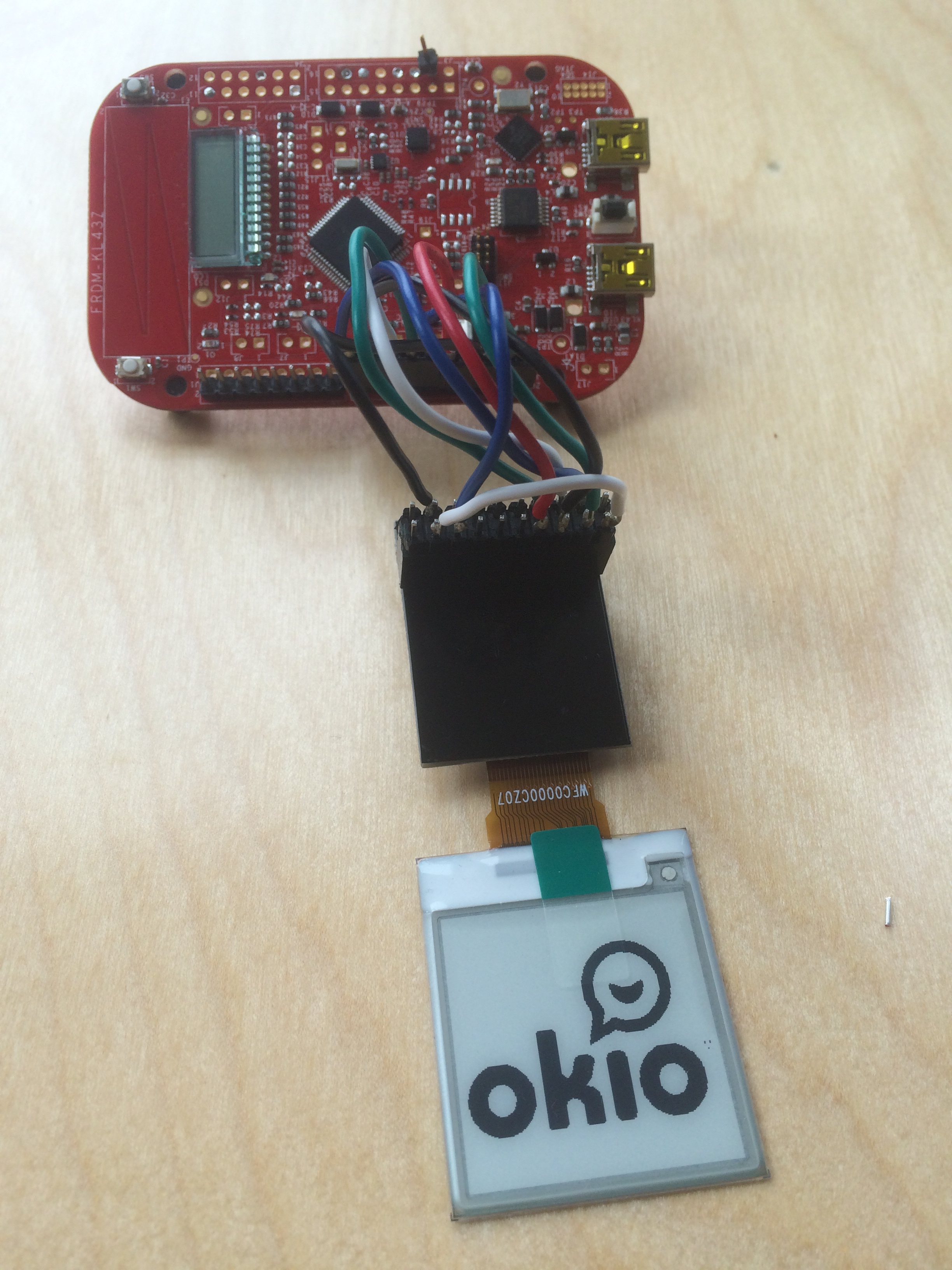
Last week I got an tiny e-ink display that I thought would be ideal for my project. I’ll document here my efforts to connect it to a Kinetis Freedom board KL43.
First the connection. The board came with a breakout connector that includes the voltage pump logic recommended by the vendor.
This is how I connected the adapter board to the freedom board. You will find the supporting documentation here.
| Board pin | MCU pin | MCU Function | Breakout board pin | |
|---|---|---|---|---|
| J2-2 | PTA13 | GPIO OUT | 4 | RESET |
| J2-4 | PTD2 | GPIO OUT | 5 | D/C |
| J2-6 | PTD4 | SSPI1 SS | 6 | CS1 |
| J2-8 | PTD6 | SPI1 MOSI | 8 | SDI |
| J2-10 | PTD7 | GPIO OUT | 16 | V3.3 |
| J2-12 | PTD5 | SPI1 CLK | 7 | SCLK |
| J2-14 | GND | - | 18 | GND |
| J2-16 | N/C | - | - | Reset |
| J2-18 | PTE0 | GPIO IN | 3 | BUSY |
| J2-20 | PTE1 | - | - | - |
Also, short BS1 to ground on the adapter, by shorting positions 1 with 17 on the jumper. This will select the more efficient 4-wire spi interface. Alternatively you could use PTE1 (J2-20) to make that option selectable.
The pinout has been chosen so that we can use the hw-accelerated spi functions. But the current version of the code is just bit-banging in software. So the SPI pins are actually configured as gpio outputs.