E-ink display at 3.3V
November 17, 2015
I’ve been experimenting with e-ink segmented displays for a new design. I could not find good documentation on how the display would behave at voltages below the recommended minimum of 5V. The results turn out to be quite good, with the caveat that you will have to allow for a longer settling time.
In the picture on the left, I turned on the background with 15V. On the right, I used 3.3V. The result is almost identical, except that in the low-voltage scenario, the display took a few seconds to “darken”.
| e-ink at 15V | e-ink at 3.3V |
|---|---|
 |
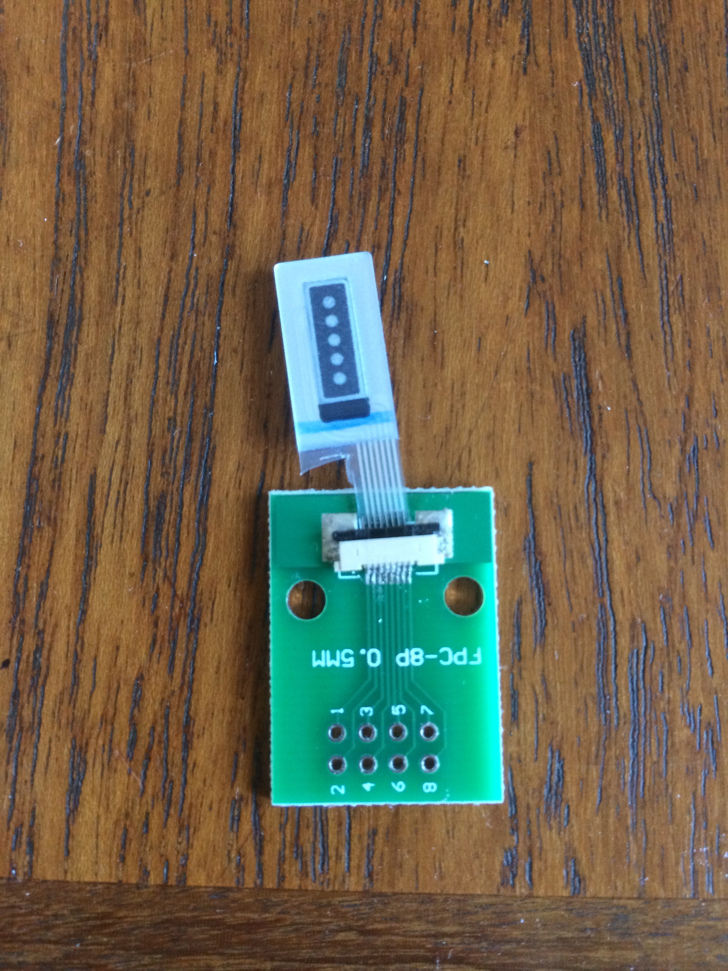 |
##Pinout This is the pin out of the breakout board. Note that I had to cut the plastic in the connector to make it fit into an 8-pin connector.
| breakout pin | function |
|---|---|
| 1 | NC |
| 2 | dot1 (top) |
| 3 | dot2 |
| 4 | dot3 |
| 5 | dot4 |
| 6 | dot5 (bottom) |
| 7 | background |
| 8 | reference electrode |
To “darken” a segment, set a positive voltage between the corresponding pin and the reference electrode. To “clear” a segment, reverse the voltage.
The pattern in the pictures is obtained by setting pin 7 to V+ (3.3 or 15V) and pin 8 to GND. It is clear by setting pin 7 to GND and pin 8 to V+.
##Parts
An X-acto knife (Try to guess from the picture above what I used that for :)